Alu-Profile Details That Make Assembly Easier
By weiyi weiyi · 2026-11-02
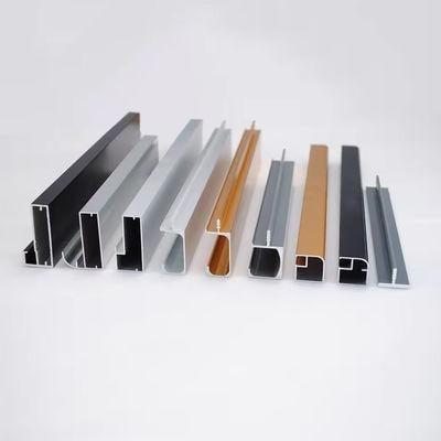
An aluminium extrusion drawing can look clean and still be difficult to assemble. Long unsupported tongues and abrupt wall-thickness transitions can complicate extrusion and dimensional control. Very thin features may distort during handling or finishing. Designers should ask which dimensions are functionally critical: a decorative radius does not deserve the same control as a sliding channel or mounting face. Put assembly dimensions on the drawing and identify the datums that a supplier should measure. Without that distinction, an inspection report can be full of numbers and still miss the reason the frame will not assemble.
Fasteners need a realistic home. Self-tapping screws, threaded inserts and corner connectors each put different loads into the extrusion. A hole shown near the edge may leave too little surrounding material; a deep slot can make it difficult for a driver to reach the fastener. If panels are inserted after frame assembly, check the access sequence before approving the cross-section. Mocking up the joints with a short length of profile is far cheaper than discovering the issue after a tooling order.
Surface treatment introduces smaller but meaningful changes. Anodising creates an oxide layer, and coating processes may alter a fit at sliding interfaces. Colour can differ across alloys, batches and surface preparations, especially when parts are viewed side by side under bright light. Specify the intended visible surfaces, acceptable appearance and which mating areas require special attention. A beautifully coated part with a jammed sliding component is not a successful finish.
On an alu-profile used for sliding parts, surface treatment can change the working gap enough to cause binding.
Prove the fit with an assembly
Long profiles also need practical handling provisions. A decorative face can be scratched by a support rack before it reaches the site. Agree which surfaces require protective film or separators and how the packing keeps profiles straight. If different lengths are cut from one design, label them in a way installers can understand. Some installation mistakes begin as packaging mistakes, long before the contractor opens a tool bag.
Consider the assembly drawing before choosing an extrusion. A cabinet rail may look right in the catalogue yet leave too little clearance for a hinge, gasket or fastener. Check whether the proposed tolerances apply to the entire length or to a short cut piece. Surface finish also matters: anodising can make handling marks apparent, while a powder-coated channel may have tighter effective clearances. Request a representative off-tool or production sample where the fit is critical. The real test is the assembled corner and its repeated use, not whether an isolated alu-profile looks straight on a table.
A practical sample review uses assembled pieces rather than loose profiles on a table. Check squareness over the intended span, corner behaviour under handling and whether the panel seats without forcing the frame. If an extrusion will support doors, lighting or suspended components, those real loads should influence the design review. The final section choice may be less visually minimal than the concept drawing. That is often a reasonable trade if it reduces deflection and installation problems.
A simple tolerance stack can make the design review much more concrete. Consider a sliding panel held between two aluminum channels. The panel width has a tolerance; so do the groove positions and any surface treatment affecting the fit. Each individual dimension may be within its allowed range while the worst-case assembly becomes tight. The team should calculate the combined variation or use a suitable statistical method, then check the most demanding assembly condition with real samples. This is different from asking whether the nominal dimensions match.
Design teams sometimes forget that the visible face of an extrusion may also become a reference surface during fabrication. If clamps, saws or drilling fixtures touch it, protection and handling plans need to account for marking. Identify which dimensions must be checked after finishing, not only before it. Any supplier proposal to change a radius or reinforce a rib should be evaluated against the assembled product: a small cross-section revision can affect the track, panel or corner hardware elsewhere in the design.