Custom Magnetic Components Manufacturer: Testing Under Load
By weiyi weiyi · 2026-11-02
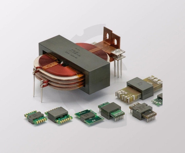
A magnetic part that meets its bench inductance target can still misbehave in a switching converter. Switching frequency, duty cycle, voltage stress and current shape determine what the magnetic part experiences.
When working with a custom magnetic components manufacturer, supply the actual waveform and mounting conditions alongside the nominal inductance target.
A DC resistance value cannot describe core losses under a high-frequency waveform, and an inductance figure without test conditions may be misleading. Specify how measurements should be performed and which parameters are critical over the operating range. Give the supplier enough circuit context to identify assumptions that affect material or geometry selection.
Saturation deserves a clear test. The relevant current is not always the average current printed in the application note; peak and transient conditions can determine whether the core remains in an acceptable region. Temperature changes material behaviour as well. If inductance collapses during a transient, the rest of the converter can see stress it was not designed to handle. Testing should use safe laboratory procedures and a circuit arrangement that represents the intended duty, not simply a low-current LCR reading.
Winding layout affects more than resistance. Leakage inductance, interwinding capacitance and coupling can influence efficiency, switching stress and electromagnetic interference.
Manufacturing variation should be considered before approving the smallest successful prototype. Winding placement, gap control and assembly tolerances can affect electrical results. Review which dimensions and process steps deserve inspection during production. If the design has no margin beyond the performance of one hand-built sample, a later yield problem should not come as a surprise.
Magnetic components are difficult to judge from inductance alone. A choke may pass an initial bench test but become too warm once ripple current and the enclosure's airflow are considered. Define the measurement conditions, expected current waveform and permissible temperature rise before approving the drawing. In power supplies, winding insulation and creepage distances also depend on the safety architecture. Test samples in a representative circuit and retain thermal photographs at steady load. Supplier discussions become clearer when the circuit requirements are documented separately from the component's nominal value.
Shielding and insulation arrangements may be needed, but they introduce trade-offs in space, cost and manufacturability. For safety-related transformers, creepage, clearance, insulation systems and applicable standards must be reviewed by qualified designers. A smaller package is not automatically a better one if it compromises required distances or thermal margin.
Heat changes the result
A useful prototype report should include both what improved and what became worse. Increasing turns might change inductance but also affect copper loss or winding space. Choosing a different core material may change losses without solving a mechanical constraint. These coupled trade-offs are why a magnetic design is rarely completed by optimising one number. Keep the design history with the samples so the team does not repeat an abandoned approach months later.
Thermal testing needs a realistic environment. A component on an open bench may run cooler than the same part enclosed beside other warm components. Measure the relevant temperatures at representative load and airflow, with attention to the worst expected operating conditions. Potting, mounting and nearby copper can change heat flow. Ask how the temperature limit is defined and whether the prototype can be built repeatably at production scale.
After the first trial, document which parameter moved the design. Did a winding change reduce loss but increase capacitance? Did a different core size improve temperature while complicating PCB placement? These are normal engineering trade-offs. The goal is a component whose electrical, mechanical, safety and production characteristics work together, with enough margin that routine manufacturing variation does not break the converter.
An engineering sample review should distinguish measurement uncertainty from real design change. Inductance readings can differ with frequency, bias and instrument setup. If two teams measure the same component under different conditions, the disagreement may be entirely procedural. Define the test fixture and relevant calibration information along with the specification. Where possible, confirm critical values on the actual converter because parasitic effects and magnetic operating points can alter the practical outcome.