LCD Display Module Manufacturer: Avoiding Integration Faults
By weiyi weiyi · 2026-11-02
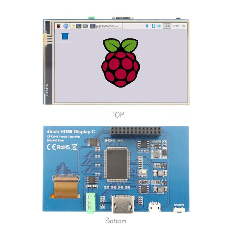
Two LCD modules with matching screen sizes can require different firmware and power timing. A module may use SPI, RGB, MIPI DSI or another protocol, and the pinout alone does not describe the full behaviour. Check signal voltage, clocking, reset timing and command sequence against the actual controller documentation. A display with the same diagonal size and resolution as another model may still use a different driver IC or initialization sequence. Copying code from a visually similar module is a common way to create an intermittent startup problem.
Watch the start-up sequence
Power sequencing matters. Logic rails, backlight supply and enable signals may need to rise in a particular order, with specified delays. Brownouts or rapid cycling can expose a reset issue that a steady bench supply hides. Use a scope or suitable instrumentation to observe rails and critical control pins at startup. Test cold start, warm reboot and power interruption rather than stopping after the first successful image.
The display's optical performance must be evaluated in the product enclosure. A panel that appears bright on a desk may be hard to read behind cover glass or under sunlight. Viewing angle, polariser choice, backlight intensity and reflections affect usability. Touch sensors, if included, introduce mechanical and electrical constraints of their own. Inspect the intended cover-glass stack and adhesive arrangement, not just an exposed panel on the engineering bench.
A display-module sample should be tested through its complete power sequence, not only after it has warmed up. Record interface timing, supply stability and the orientation expected in the final enclosure. A panel that renders a sharp laboratory image may be unreadable in direct sunlight or show uneven brightness in a product housing. Check touch performance where applicable and review long-term availability before releasing tooling. When discussing a custom LCD display module, identify which parts are truly customised and which rely on a controller or driver with its own lifecycle.
A module supplier should be able to clarify what the stated viewing-angle, brightness and operating-temperature figures actually describe. Values may be measured under particular test conditions and may not predict appearance behind a tinted cover. Use the application's real readability requirement to decide what to test. If the product must show small text outdoors, a glossy demo on an indoor evaluation board is a poor substitute for a representative enclosure trial.
Mechanical integration often reveals late surprises. Flexible cables need a sensible bend path and strain relief. Mounting pressure can distort the display or create visible light leakage. Connector orientation affects assembly order, and the display's active area must align with the window. Allow room for tolerances between PCB, enclosure and module. A drawing with only external dimensions may be insufficient to ensure a reliable fit.
An LCD display module manufacturer may supply several panels with the same visible size but different connector orientations or flex-cable paths.
A useful display test harness can expose a few status screens before the product's complete application is ready. Show solid colours, gradients, fine lines and images that make clipping or colour-order errors visible. Exercise the backlight at different settings and record any unusual flicker. These basic patterns help separate panel or interface faults from application-layer rendering issues, which can save days of searching through unrelated firmware modules.
Build a small test matrix that covers the operating states most likely to fail: startup, sleep, wake, maximum brightness and temperature extremes within the specified range. Record firmware and module revisions alongside results. An LCD sample is not fully approved because it shows a colourful demonstration image. It is approved when the intended product can drive, power and physically house it reliably through realistic use.
Supplier change control matters after prototype approval. A revised driver IC, flex tail or backlight unit may require new firmware or mechanical checks even when the catalogue model name stays the same. Ask how revisions are identified and communicated, and retain approved samples with their corresponding software release.